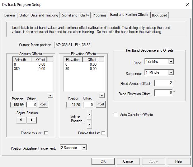
| The left hand side of the dialog is where
you can set up what I call 'Positional Offsets'. This is for
when there is some anomaly in the rotation of your antenna, for
either Azimuth or Elevation. Consider what happens if the gear
or pulley that drives your Azimuth encoder is not mounted at the
exact center of rotation of the antenna mount. This will cause
slight variations in the encoder output value as the antenna is
turned. Normally these variations are very small and can be
ignored, but when operating on a high microwave band with a large
dish antenna, even a few tenths of a degree error can cause loss of
signal. A similar problem exists when the antenna mount is not
perfectly aligned with the surface of the earth. This means
that the rotating mast will be tilted a slight amount in some
direction. When the antenna rotates the tilt will cause the
beam to be low in some directions and high in others.
Another example is that the potentiometer or other encoder you
are using exhibits some non-linear characteristics. For
example, when the antenna is horizontal, the reading is correct,
but as you elevate the antenna the reading becomes more and more
in error.
Positional Offsets are designed to adjust for such
anomalies. It is complicated to think about how this works,
and often two people discussing it find that they both are saying
something different but meaning the same thing. So it is
impossible for me to design a system that will be the way every
person thinks. Instead I have picked a scheme and provided
several ways to enter, or measure and enter the offsets. I
hope this explanation will make sense to most of you.
Positional Offsets use data tables that are entered by the
operator and saved on the computer (not in the controller).
The saved data contains values for various points in the rotation
or elevation of the antenna. Each point contains the number
of degrees for the point and the offset at that point. The
DrzTrack program will interpolate between these points to
determine the correct offset to apply at any given antenna
position. Any fixed band offsets will also be added at the
same time, so the total offset will be Band Offset + Position
Offset.
For Azimuth the first point must be at zero degrees and the last
position must be 360 degrees. For Elevation the start and
end are at zero and 90 degrees. All points in the table are
at even numbered degrees (fractional degree values will be
rounded). A point may be entered for each degree in the range
0-360 or 0-90, however in practice no more than 4 or 5 points
should be needed because the program interpolates between points
and usually the offset change will be linear, or fairly linear
over a quarter turn.
Once the table is created and saved (by pressing Apply or OK), it
must be enabled before it will be used. Check the box
'Enable this List' to start using the offset table.
Ok, now that you understand the tables, here is how to enter
them. There are three methods:
1) Probably the simplest way is to click the little + button just
below each table. This will bring up a window where you can
enter a position and offset. It is not necessary to enter
the positions in any special order, they will be added to the
table in order by degree. This method can only be used if
you already know what your antenna offset is at the various
positions.
2) You can rotate your antenna to each position and then measure
the offset. When you use this method you then enter the
measured offset in the 'Offset' field below the table and then
click the 'Set' button. This adds the point and current
position to the table.
3) Measuring the offset may be difficult. You can try to
bore sight it against a known object such as the Sun or Moon, but
it is easier to use method 3, where the offset is automatically
calculated for you. To the right of the two tables is a
check box labeled 'Auto-Calculate Offsets'. When that box is
checked the difference between the position that the encoder
measures and the current position of the antenna will be
shown. By rotating the antenna so it is pointed at the Sun
or Moon, either by observation, or possibly by measuring Sun or
Moon noise, the actual offset will be displayed in the Offset
field and you can simply click the Set button to save it. Of
course this method requires that you measure when the Sun or Moon
is at various positions in the rotation of the antenna and so
might take days to accomplish. However as each new offset
value is added to the table the aiming will become more accurate,
so you can enter one or two points and then add more points as
they are encountered.
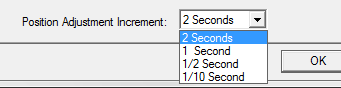 When using method 3 very precise
positioning of the antenna is required, so I have provided a way
to 'Jog' the antenna by small amounts to get it correctly
placed. To jog the antenna you click one of the four arrow
buttons. Each click turns on the motor for a short
time. The time the motor is on is controlled by the
'Position Adjustment Increment' drop down box. The choices
are 2, 1, 1/2, and 1/10 of a second. Of course if you have
switches to manually control your antenna you can use those
instead. When using method 3 very precise
positioning of the antenna is required, so I have provided a way
to 'Jog' the antenna by small amounts to get it correctly
placed. To jog the antenna you click one of the four arrow
buttons. Each click turns on the motor for a short
time. The time the motor is on is controlled by the
'Position Adjustment Increment' drop down box. The choices
are 2, 1, 1/2, and 1/10 of a second. Of course if you have
switches to manually control your antenna you can use those
instead.
 Be sure to enable your tables.
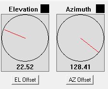
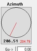
When you are done, click OK and return to the main
window. Now the offset position will be shown on the
compass in black numerals and the actual antenna position as
measured by the encoders will be shown in red numerals. Be sure to enable your tables.
When you are done, click OK and return to the main
window. Now the offset position will be shown on the
compass in black numerals and the actual antenna position as
measured by the encoders will be shown in red numerals. |
Also note that the LCD display on the encoder will continue to
display the exact readout from the encoders, and will not include
either positional or band offsets. There is a checkbox in
the 'General' tab of the Setup dialog that can be used to cause
the LCD to display the offset position rather that the encoder
position. See the above description of feature
checkboxes.
|
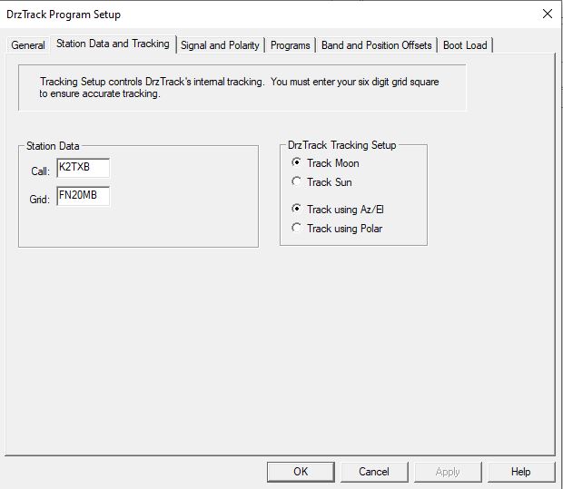
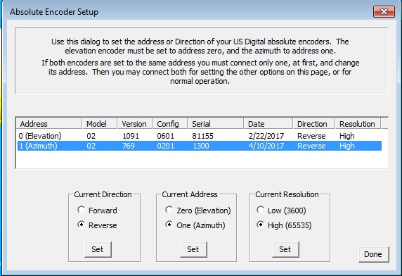
 Note that this screen is separated into
upper and lower sections. The upper section could be called
the mount section. It is where you select the encoder types
and calibration and tracking ranges and other settings that are
specific to the mount.
Note that this screen is separated into
upper and lower sections. The upper section could be called
the mount section. It is where you select the encoder types
and calibration and tracking ranges and other settings that are
specific to the mount.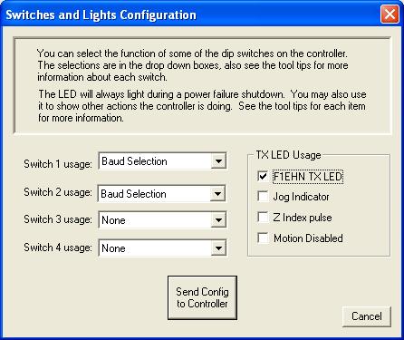
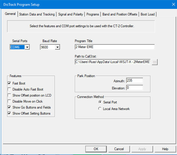
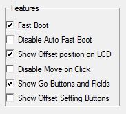 1. Fast Boot. When
checked, the display of boot messages in the main dialog, and on
the LCD display (if present) is greatly speeded up.
1. Fast Boot. When
checked, the display of boot messages in the main dialog, and on
the LCD display (if present) is greatly speeded up.