|
If you are using DC motors for antenna movement then you can use an
H-Bridge instead of relays to control the motors.
An H-bridge is a device that controls the speed and
direction of a DC motor, by routing current in opposite directions.
It allows low-power control signals from the controller to drive
higher-power motors. They also
can
use Pulse Width Modulation (PWM)
for speed control, and include diodes to
protect against inductive kickback.
The CT-2 controller will work with certain types of H-Bridges and by
using the jogging feature, true PWM speed control can be realized.
When selecting an H-Bridge to use with the CT-2, several factors need to
be considered:
1. Look for a full bridge device, not a half bridge.
2. If you want to control both azimuth and elevation motors with a
bridge, look at dual H-Bridges. That will simplify the wiring.
3. When using a dual bridge, both motors must be powered from the same
power source.
4. The bridges must be controllable with just two input lines for each
direction (two for up/down and two for CW/CCW).
5. The bridges must stop the motors when both inputs are high as well as
when they are both low.
6. The bridge input lines must be pulled high. If they are not
then use pull-up resistors to assure the lines are high when not being
controlled.
We have tested the CT-2 with three different bridges, detailed below.
One thing to keep in mind is that the bridge must be able to handle the
stall current of your motor. It is a good idea to measure the
stall current yourself so you are sure how much current capacity you
need. |


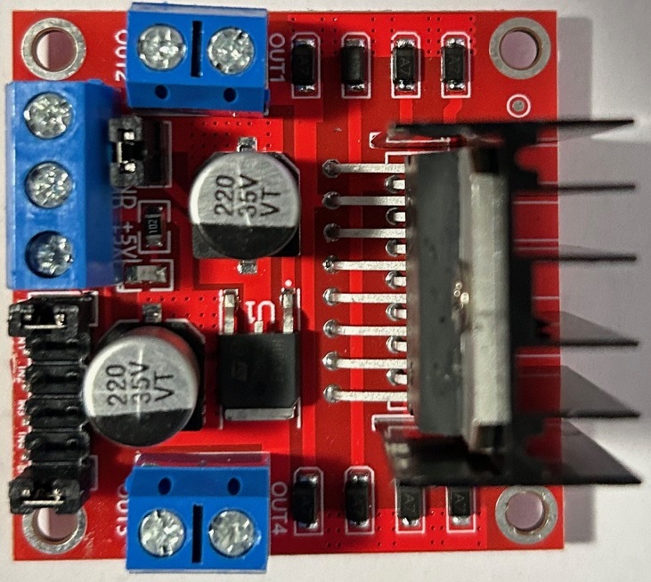
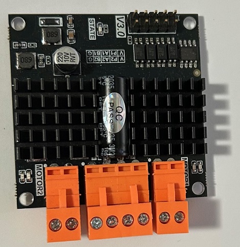
 This
is a 7 amp H-Bridge, available from EBay, for about eight dollars. It
is EBay Item 182484648130. It can handle 6.5 to 27 volts at 7 amps.
Price is currently about 7 dollars
This
is a 7 amp H-Bridge, available from EBay, for about eight dollars. It
is EBay Item 182484648130. It can handle 6.5 to 27 volts at 7 amps.
Price is currently about 7 dollars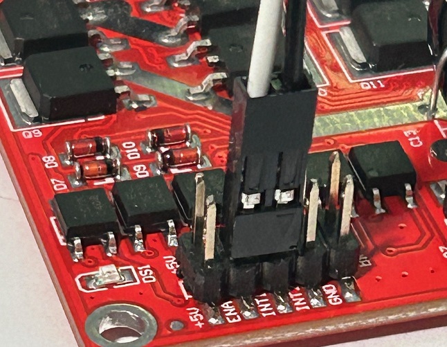
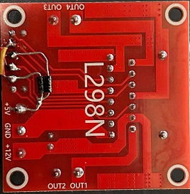
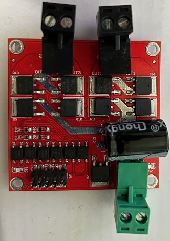
 If
you really have a big motor, you can use this 12 amp H-Bridge. It is
available from Digikey for about 29 dollars. Here is the link:
If
you really have a big motor, you can use this 12 amp H-Bridge. It is
available from Digikey for about 29 dollars. Here is the link: