| This is the hardware page for Absolute
Position Encoders. To find information about selecting the various types of these
encoders, please refer to the
Encoders
page. And find more information on these pages: Calibration - Detailed Configuration. J1, the RJ12 connector, is for connection to absolute encoders. These encoders supply absolute position information to the controller board once they are calibrated by setting the range and position. There are three makes of absolute encoders that can be used with the CT-2 controller, detailed below. Addressing: The encoders are normally shipped set to address zero. This is correct for the elevation encoder but the azimuth encoder must be programmed to use address one. Newer versions of DrzTrack have the capability of reprogramming the encoders. You can set the address, reverse direction, and select low or high resolution. For details on how to do this refer to our Absolute Encoder Programming page. Or, for the US Digital devices, you can order the encoder pre-programmed for the addresses you need, or you can buy a USB to SEI bus adapter and software from US digital so you can program the encoders yourself. |
|---|
| The US Digital
A2 encoder
can be used for azimuth or elevation with suitable gearing, but it is
easier to use the
A2T
encoder
for elevation because it is an inclinometer (works via gravity rather
than being driven by a shaft).
To order these parts you must work up the part number by combining the options you want. Their web page gives all the particulars. We do recommend the sealed housings to help keep out moisture. For the Azimuth encoder we recommend the A2-S-B-D-M-S. The part number was derived as follows: Series = A2, S = SEI buss, B = Ball Bearing, D = Default shaft extension, M = Includes mounting plate, S = Sealed Housing. Note 1. For the inclinometer the part number is A2T-S-D-S. Series = A2T, S = SEI buss, D = Double Damping, S = Sealed housing. 
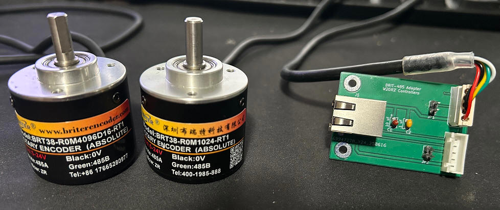
When you buy A2 encoders, you can order wires with connectors in the length you need (see the cable information below).. The connector on the wire kit will plug directly into J1 on the CT-2. If you are using the absolute encoders for both azimuth and elevation then you will need 3 of the wires and a 'Y' adaptor. Note 2.
Alternatively you can buy wire, connectors and a crimp tool for RJ12 connectors and make up the wiring yourself. You will still need the Y adaptor if you are using two A2 encoders. Note 1: US Digital has eliminated the option to order encoders with a sealed housing. So the new part number for the A2 encoder is A2-S-B-D-M-D, and A2T-S-D-D for the inclinometer. Note 2: US Digital does not seem to carry the Y adaptors any more. Maybe they do but not on their web pages. I found some on Amazon, but could not link the page here. Be very careful when ordering, the part must be specified as 6P6C for six wire connectors. Most Y adaptors on the market are for 4 pins and will not work for the absolute encoders.
|
| Here is the link to the manufacturers web pages:
https://briterencoder.com/product/absolute-rotary-encoder-with-rs485-modbus-rtu-communication On that page, select "single turn", and either 10 bit(1024) or 12 bit(4096), and "6mm Solid Shaft". The 6mm shaft is about the same as a 1/4" standard shaft. Other sizes are available depending on your requirements. The current prices (Jan 2026) are $43.83 for low resolution, or $114 for high resolution. The photo below shows both encoder types and the adapter board required to use them with our CT-2 controller.
The wiring between the CT-2 and the BRIT-485 adapter board is standard 6 conductor twisted pair with RJ12 male connectors on each end. It does not matter which connector is used for elevation or azimuth. The same data lines are used for each. You do need to keep track of which is which, because JP1 and JP2 are used to reset the controllers, thus you need to know which one to connect if you need to reset a controller. The encoders can be ordered with custom cable lengths, so make them long enough so they both can reach the location of the adapter board. Also, see the cable information below. The adapter board shown is a test version. Production versions will have 2 more mounting holes to make sure it is easy to plug in the encoder cables without damaging the board, If both encoders are close together then a single board will suffice. If your cables are not long enough to reach the adapter board you can use two adapter boards and a Y as shown for the US Digital encoders, above. Alternatively you could cut and extend one or both of the cables from the encoders. Make sure the encoder cables do not exceed 10 feet in length. |
| The adapter board is part number BRT-485, and is sold for $15.
It replaces the use of a Y adapter, while allowing use of the standard
connector that the encoders are supplied with, It also has two
jumper positions P1 and P2 that are used to reset a controller if
needed. It comes with 2 little shorting plugs. To do a reset, power down the encoder (*) and put one of the shorting plugs on the jumper for the encoder needing resetting. Then power the encoder up and wait for 2 full minutes. Then power off and remove the jumper. That will reset the encoder to the factory default settings. You may need to reset the address and direction. See the programming information for details. * Power down is most easily done by unplugging the RJ12 from the adapter board. |
| The part numbers are ETS25 or MAB25. The MAB25 is a
discontinued item, but will work well if you find some. The part number to order is ETS25 6x22 05SER LA. They are about $50 each. The 6x22 indicates the shaft size (6.35 by 22 mm), 05SER indicates it is a 5 volt part and has a serial interface (do not order the ones that they advertise as an absolute interface), and LA indicates that the connection to the device is solder pads.
The designation for the adaptor board is MABMPU and can be ordered from Gary, N8CQ, Here are photos of the front and back of the board. The two RJ12 connectors are connected in parallel, so if you have two absolute encoders you can route them through and the board becomes the Y adaptor. Plus 12 VDC is applied to the board from the Drz Control CT-2 board, via the RJ12 Jack. The board has it's own 5 volt regulator for the encoder. As with the US Digital encoders, you can make your own cables or order wires with connectors in the length you need. See the cable information below.
This is the bottom of the board. If desired you can mount the ET25 encoder directly on the board by sliding the pins through the through holes on the connection pads on the encoder. The bottom of the encoder will sit where the white circle is. This is a good arrangement if you are able to house the board and the encoder in the same location. Below is a photo of another way to make the connection. In this case I was putting the encoder directly in a Yaesu G800 rotator, replacing the potentiometer. There was not room inside the rotator for the board so I used a short length of flat wire to go from the encoder to the existing G800 connector, then about 4 feet of normal rotator cable from the rotator to my relay box on the tower, where the MabMpu board is housed. A US Digital inclinometer is installed above the G800 and it's cable runs down past the G800 and into the same box, where it plugs into the MabMpu board. Then the main encoder cable runs from the MabMpu board, down to the shack and connects to the W2DRZ CT-2 controller. This works fine, but for any longer run I suspect that twisted pair wiring would be needed between the rotator and the MabMpu board.
|
| This section details the cable
specifications for the US Digital, BriterEncoder, and Megatron encoders. The cables between the absolute encoders and the CT-2 have six conductors consisting of 3 twisted pairs. Using twisted pair wiring is required when the encoders are a long distance from the controller (over 10 feet). Care is required when ordering or making these cables because the US Digital connection standards do not match standard Telco cables that can be purchased ready-made. In particular, pins 2 and 3 and pins 5 and 6 must be on a twisted pair. For standard 6 conductor cables this means that pins 2 and 3 should use the green and green/white pair, and pins 5 and 6 should use the blue and blue/white pair. See the chart below. Matching cables can be bought from US Digital (US Digital part CA-MD6-SH-MD6-XX.). Otherwise it is best to make up the cables yourself to be sure the pairs are used correctly. When making your own cables, an RJ12 crimping tool is required. Also it is highly advised to get a line tester to check the completed cables. A quick search shows numerous options for suitable cable testers ranging in price from $8 to around $30. Any of those should do. Just search for 'network cable testers' and make sure the tester you select can do RJ12 connectors as one of its options.
|